Difference between revisions of "Raspberry Pi and Sensors"
Jump to navigation
Jump to search
| Line 1: | Line 1: | ||
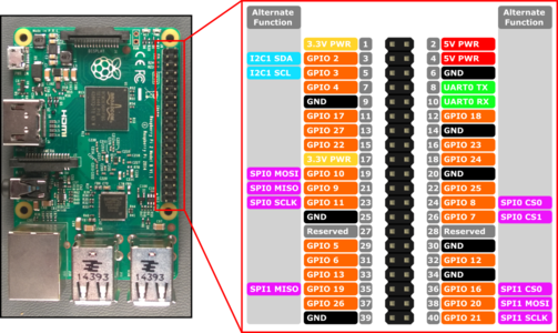
| − | + | [[File:RPI3_Pinout.png|right|thumb|x300px|alt=A Raspberry Pi 3 Pinout|A Raspberry Pi 3 Pinout]] | |
| + | In this activity, we are going to integrate a HC-SR04 Ultrasonic Module Distance Measuring Sensor to measure distance. Modern self-driving cars can use ultrasonic in conjunction with other sensors which may include radar, cameras, GPS and potentially LIDAR. In some cases, ultra sonic sensors can be more reliably that other proximity sensor for detecting movement in an area, such as the presence of a person in a room. | ||
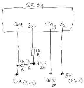
| − | + | Lets get started by referring to the Raspberry Pi pinout. Then, carefully examine the circuit diagram that we will be using below. | |
| − | |||
| − | |||
| − | |||
| − | |||
| − | |||
| − | |||
| − | |||
[[File:sr04_circuit.jpeg|right|thumb|x300px|alt=A circuit diagram of the SR04 Wiring|A circuit diagram of the SR04 Wiring]] | [[File:sr04_circuit.jpeg|right|thumb|x300px|alt=A circuit diagram of the SR04 Wiring|A circuit diagram of the SR04 Wiring]] | ||
Revision as of 12:36, 19 July 2020
In this activity, we are going to integrate a HC-SR04 Ultrasonic Module Distance Measuring Sensor to measure distance. Modern self-driving cars can use ultrasonic in conjunction with other sensors which may include radar, cameras, GPS and potentially LIDAR. In some cases, ultra sonic sensors can be more reliably that other proximity sensor for detecting movement in an area, such as the presence of a person in a room.
Lets get started by referring to the Raspberry Pi pinout. Then, carefully examine the circuit diagram that we will be using below.
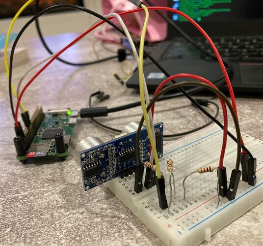
Finally, examine the picture below to confirm your understanding. You may want to click on ti to get a high res version.
#!/usr/bin/python3

import RPi.GPIO as GPIO
import time

GPIO.setmode(GPIO.BCM)

TRIG = 23
ECHO = 24

print("Distance Measurement In Progress")

GPIO.setup(TRIG,GPIO.OUT)
GPIO.setup(ECHO,GPIO.IN)

GPIO.output(TRIG, False)

print("Waiting For Sensor To Settle")

time.sleep(2)

GPIO.output(TRIG, True)
time.sleep(0.00001)

GPIO.output(TRIG, False)

while GPIO.input(ECHO)==0:

  pulse_start = time.time()

while GPIO.input(ECHO)==1:

  pulse_end = time.time()

pulse_duration = pulse_end - pulse_start

distance = pulse_duration * 17150

distance = round(distance, 2)

print("Distance:",distance,"cm")

GPIO.cleanup()


