Difference between revisions of "Raspberry Pi and Sensors"
| (19 intermediate revisions by the same user not shown) | |||
| Line 1: | Line 1: | ||
| − | = | + | [[File:RPI3_Pinout.png|right|thumb|x300px|alt=A Raspberry Pi 3 Pinout|A Raspberry Pi 3 Pinout]] |
| + | |||
| + | In this activity, we will explore two different types of sensors on the raspberry pi. The first type is using a sensor communication mechanism called I2C (Inter-Integrated Circuit (I^2C). This is a serial like communication protocol and we will use this with the ambient light sensor. The second sensor will just use the GPIO (General Purpose Input/Output) ports on the Pi, and the distance sensor we use is much cheaper to produce, but more complex to wire. There is another type of communication called SPI (Serial Peripheral Interface) which can be used instead of I2C in some cases. If you look at the pinout you will notice MOSI, MISO, CLK, CS0 and CS1, which can be used for communicating with an SPI sensor. | ||
| + | |||
| + | You will need to familiarise yourself with the pinout. Please be very careful with connecting things to the pi. A wrong move can badly fry your Raspberry Pi, you have been warned! | ||
| − | [[File: | + | == The Ambient Light Sensor == |
| + | |||
| + | In this activity, we will show you how to use an I2C sensor. The sensor that we are using is an ambient light sensor. Ambient light sensors might be useful in digital agriculture scenarios where you may want to track the amount of light provided to an indoor or outdoor plant. Alternatively, it could be used in buildings to manage the blinds and the amount of LED lighting added to a room. | ||
| + | |||
| + | [[File:Light_sensor.jpg|right|thumb|x450px|alt=The light sensor|The light sensor]] | ||
| + | |||
| + | This is nicely colour coded and you can use the image to the right as a guide. I haven't provided a detailed diagram past the photos because it is relatively simple. There are 4 wires and you can refer to the pinout above: | ||
| + | *Connect VCC to 3.3v | ||
| + | *Connect GND to ground | ||
| + | *Connect SCL to SCL and | ||
| + | *Connect SDA to SDA | ||
| + | |||
| + | Lets start by making sure that I2C is enabled on the pi. Type: | ||
| + | |||
| + | sudo raspi-config | ||
| + | |||
| + | Then go to: | ||
| + | |||
| + | Interface options -> I2C | ||
| + | |||
| + | And make sure this is turned on. You may need to reboot. | ||
| + | |||
| + | You then want to ensure you have the python packages so: | ||
| + | |||
| + | sudo pip3 install adafruit-circuitpython-veml7700 | ||
| + | |||
| + | Then, you should use your favourite text editor to create the following program: | ||
| + | |||
| + | nano gravity_ambient_light.py | ||
| + | |||
| + | <pre> | ||
| + | #!/usr/bin/python3 | ||
| + | import time | ||
| + | import board | ||
| + | import busio | ||
| + | import adafruit_veml7700 | ||
| + | |||
| + | i2c = busio.I2C(board.SCL, board.SDA) | ||
| + | veml7700 = adafruit_veml7700.VEML7700(i2c) | ||
| + | |||
| + | while True: | ||
| + | print("Ambient light:", veml7700.light) | ||
| + | time.sleep(0.1) | ||
| + | </pre> | ||
| + | |||
| + | You can then run the program and sense the ambient light with: | ||
| + | |||
| + | python3 gravity_ambient_light.py | ||
| + | |||
| + | Move your hand over the sensor to change the amount of ambient light. | ||
| + | |||
| + | == The Ultrasound Sensor == | ||
In this activity, we are going to integrate an HC-SR04 Ultrasonic Module Distance Measuring Sensor to measure distance. Modern self-driving cars can use ultrasonic in conjunction with other sensors which may include radar, cameras, GPS and potentially LIDAR. In some cases, ultrasonic sensors can be more reliable than other proximity sensor for detecting movement in an area, such as the presence of a person in a room. | In this activity, we are going to integrate an HC-SR04 Ultrasonic Module Distance Measuring Sensor to measure distance. Modern self-driving cars can use ultrasonic in conjunction with other sensors which may include radar, cameras, GPS and potentially LIDAR. In some cases, ultrasonic sensors can be more reliable than other proximity sensor for detecting movement in an area, such as the presence of a person in a room. | ||
| Line 24: | Line 79: | ||
[[File:sr04_picture.jpeg|right|thumb|x500px|alt=A picture of a Raspberry Pi Zero, wired to an SR04|A picture of a Raspberry Pi Zero, wired to an SR04]] | [[File:sr04_picture.jpeg|right|thumb|x500px|alt=A picture of a Raspberry Pi Zero, wired to an SR04|A picture of a Raspberry Pi Zero, wired to an SR04]] | ||
| + | |||
| + | [[File:distance_sensor.jpeg|right|thumb|x500px|alt=Another picture of a Raspberry Pi Zero, wired to an SR04|Another picture of a Raspberry Pi Zero, wired to an SR04]] | ||
=== The Python 3 code === | === The Python 3 code === | ||
| Line 79: | Line 136: | ||
Make sure you play around with distances to ensure your sensor is working properly. | Make sure you play around with distances to ensure your sensor is working properly. | ||
| − | == Challenge 1 | + | == Challenge 1 == |
*Can you loop over this code continually? | *Can you loop over this code continually? | ||
| Line 87: | Line 144: | ||
Review one of the early labs, called [[Contactless Doorbell with If This Then That]], where you setup a webhooks trigger that sent an email. | Review one of the early labs, called [[Contactless Doorbell with If This Then That]], where you setup a webhooks trigger that sent an email. | ||
| − | Set up a new webhooks trigger called distance. Can you integrate the following python3 code to make your Raspberry Pi trigger the webhook to send you an email when someone is within 10 cm of the sensor | + | Set up a new webhooks trigger called distance. Can you integrate the following python3 code to make your Raspberry Pi trigger the webhook to send you an email when someone is within 10 cm of the sensor? |
<pre> | <pre> | ||
| − | import | + | import urllib.request as req |
if distance < 10: | if distance < 10: | ||
| − | + | print(req.urlopen("https://maker.ifttt.com/trigger/proximity/with/key/this-is-your-url").status) | |
print("The object is closer than 10 cm, firing up IFTTT") | print("The object is closer than 10 cm, firing up IFTTT") | ||
</pre> | </pre> | ||
Latest revision as of 01:39, 4 October 2021
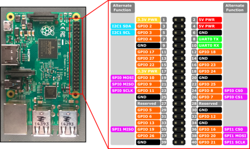
In this activity, we will explore two different types of sensors on the raspberry pi. The first type is using a sensor communication mechanism called I2C (Inter-Integrated Circuit (I^2C). This is a serial like communication protocol and we will use this with the ambient light sensor. The second sensor will just use the GPIO (General Purpose Input/Output) ports on the Pi, and the distance sensor we use is much cheaper to produce, but more complex to wire. There is another type of communication called SPI (Serial Peripheral Interface) which can be used instead of I2C in some cases. If you look at the pinout you will notice MOSI, MISO, CLK, CS0 and CS1, which can be used for communicating with an SPI sensor.
You will need to familiarise yourself with the pinout. Please be very careful with connecting things to the pi. A wrong move can badly fry your Raspberry Pi, you have been warned!
Contents
The Ambient Light Sensor
In this activity, we will show you how to use an I2C sensor. The sensor that we are using is an ambient light sensor. Ambient light sensors might be useful in digital agriculture scenarios where you may want to track the amount of light provided to an indoor or outdoor plant. Alternatively, it could be used in buildings to manage the blinds and the amount of LED lighting added to a room.
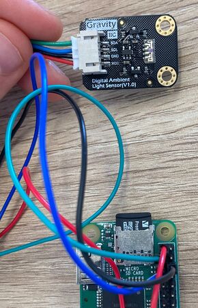
This is nicely colour coded and you can use the image to the right as a guide. I haven't provided a detailed diagram past the photos because it is relatively simple. There are 4 wires and you can refer to the pinout above:
- Connect VCC to 3.3v
- Connect GND to ground
- Connect SCL to SCL and
- Connect SDA to SDA
Lets start by making sure that I2C is enabled on the pi. Type:
sudo raspi-config
Then go to:
Interface options -> I2C
And make sure this is turned on. You may need to reboot.
You then want to ensure you have the python packages so:
sudo pip3 install adafruit-circuitpython-veml7700
Then, you should use your favourite text editor to create the following program:
nano gravity_ambient_light.py
#!/usr/bin/python3
import time
import board
import busio
import adafruit_veml7700

i2c = busio.I2C(board.SCL, board.SDA)
veml7700 = adafruit_veml7700.VEML7700(i2c)

while True:
    print("Ambient light:", veml7700.light)
    time.sleep(0.1)
You can then run the program and sense the ambient light with:
python3 gravity_ambient_light.py
Move your hand over the sensor to change the amount of ambient light.
The Ultrasound Sensor
In this activity, we are going to integrate an HC-SR04 Ultrasonic Module Distance Measuring Sensor to measure distance. Modern self-driving cars can use ultrasonic in conjunction with other sensors which may include radar, cameras, GPS and potentially LIDAR. In some cases, ultrasonic sensors can be more reliable than other proximity sensor for detecting movement in an area, such as the presence of a person in a room.
Note, this activity was designed based on the guide here
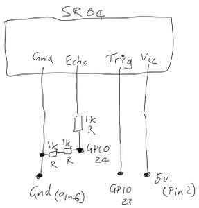
Let's get started by referring to the Raspberry Pi pinout. Then, carefully examine the circuit diagram that we will be using below.
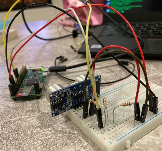
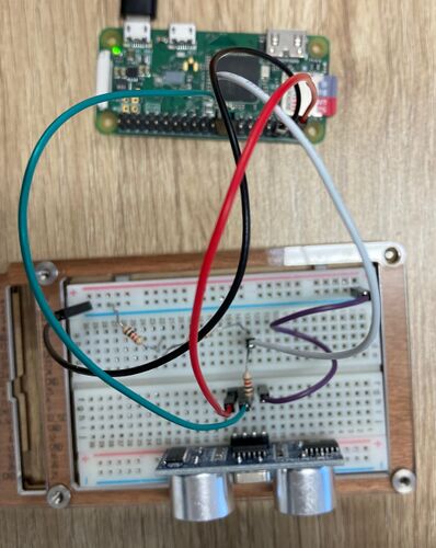
Finally, examine the picture, of my SR04 wired up, below to confirm your understanding. You may want to click on it to get a high res version. Note that to reduce the number of resistors we were required to purchase, I have used 2 x 1k Resistors rather than a single 1k resistor.
Please read here for a more thorough description of the electronics used in this activity.
Put simply, ultrasound relies on sound waves, so picture a speaker making a sound wave that hits a surface and reflects back and is then received by a microphone. The sounds are not audible to us as they are a higher frequency than we can hear.
These ultrasound sensors will measure the time duration between when the ultrasound signal is sent out, and when it is received back. Working out the distance of the object from the sensor will require us to understand the speed of sound.
The speed of sound is 343m per second. Now the unit we are using is cm so let's multiply 343 by 100 to get to cm, so 34300. Now, the signal we will send out will need to hit a surface and bounce back so to prevent the distances from appearing twice as far, lets divide 34300 by 2 to get 17150.
Now that you understand where that value is coming from, read the Python 3 code below and see if you can get an idea of what is going on.
The Python 3 code
#!/usr/bin/python3

import RPi.GPIO as GPIO
import time

GPIO.setmode(GPIO.BCM)

TRIG = 23
ECHO = 24

print("Distance Measurement In Progress")

GPIO.setup(TRIG,GPIO.OUT)
GPIO.setup(ECHO,GPIO.IN)

GPIO.output(TRIG, False)

print("Waiting For Sensor To Settle")

time.sleep(2)

GPIO.output(TRIG, True)
time.sleep(0.00001)

GPIO.output(TRIG, False)

while GPIO.input(ECHO)==0:

  pulse_start = time.time()

while GPIO.input(ECHO)==1:

  pulse_end = time.time()

pulse_duration = pulse_end - pulse_start

distance = pulse_duration * 17150

distance = round(distance, 2)

print("Distance:",distance,"cm")

GPIO.cleanup()
Use the code above and your favourite text editor, and save it as distance_sensor.py, then run.
python3 distance_sensor.py
Make sure you play around with distances to ensure your sensor is working properly.
Challenge 1
- Can you loop over this code continually?
Challenge 2
Review one of the early labs, called Contactless Doorbell with If This Then That, where you setup a webhooks trigger that sent an email.
Set up a new webhooks trigger called distance. Can you integrate the following python3 code to make your Raspberry Pi trigger the webhook to send you an email when someone is within 10 cm of the sensor?
import urllib.request as req

    if distance < 10:
        print(req.urlopen("https://maker.ifttt.com/trigger/proximity/with/key/this-is-your-url").status)
        print("The object is closer than 10 cm, firing up IFTTT")
