EVE ACL Challenge
Contents
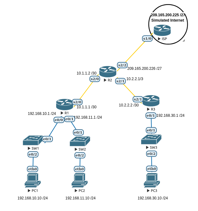
EVE Starting Topology
Topology
Addressing Table
Device         Interface          IP Address        Subnet Mask         Default Gateway
                 e0/0            192.168.10.1       255.255.255.0
R1               e0/1            192.168.11.1       255.255.255.0
                 s2/0            10.1.1.1           255.255.255.252

                 s2/0            10.1.1.2           255.255.255.252
R2               s2/1            10.2.2.1           255.255.255.252
                 S2/2            209.165.200.226    255.255.255.224

                 e0/1            192.168.30.1       255.255.255.0
R3               s2/1            10.2.2.2           255.255.255.252

ISP              s1/0            209.165.200.226    255.255.255.224

PC1              NIC             192.168.10.10      255.255.255.0        192.168.10.1

PC2              NIC             192.168.11.10      255.255.255.0        192.168.11.1

PC3              NIC             192.168.30.10      255.255.255.0        192.168.30.1
Learning Objectives
- With reference to the Basic ACL Lab design and configure your own rules to deliver the security policies outlined below.
Reflections from the unit coordinator in previous years ...
- Depending on the errors made, many students will break OSPF communications and thus all communications fail. It's a good learning experience but only if students eventually figure out what has happened. Many students assume the lack of communications is because the ACL is blocking their packets. In reality, the router has no route because OSPF is down.
Preparation
In this lab all the initial configuration has already been applied.
- Load the EVE Topology and ensure that there is end-to-end connectivity with the ping command.
Security Policies
There are three individual policies outlined here. Your task is to use Access Control Lists to deliver the necessary security outcome.
Policy 1
No users on the 192.168.10.0 /24 network may send packets to the R2 address 10.1.1.2
- Design an appropriate ACL, apply and test it.
- Consider:
- Standard or Extended ACL?
- Where is it best applied.
There may be multiple answers depending on your assumptions. Discuss the options and your thoughts with your peers or the tutor.
Policy 2
Only users on the 192.168.11.0 /24 network may Telnet to 209.165.200.225
- Design an appropriate ACL, apply and test it.
- Consider:
- Standard or Extended ACL?
- Where is it best applied.
- This can be achieved with "access-groups" and "access-classes". Use either method but understand both.
- Careful to distinguish between IP and TCP.
There may be multiple answers depending on your assumptions. Discuss the options and your thoughts with your peers or the tutor.
Note that in EVE the Virtual PCs support a "ping" command that can be used to test TCP and UDP ports. To see the options try:
PC2> ping help
To test Telnet (port 23) connectivity to 209.165.200.225:
PC2> ping 209.165.200.225 -3 -p 23
Policy 3
Users on IP addresses between 192.168.30.32 and 192.168.30.40 may not ping the Internet Loopback address
- Design an appropriate ACL, apply and test it.
- Consider:
- Standard or Extended ACL?
- Where is it best applied.
- Remember the "implicit deny"
There may be multiple answers depending on your assumptions. Discuss the options and your thoughts with your peers or the tutor.
Initial Device Configurations
PC1
ip 192.168.10.10/24 192.168.10.1
PC2
ip 192.168.11.10/24 192.168.11.1
PC3
ip 192.168.30.10/24 192.168.30.1
R1
hostname R1
interface Ethernet0/0
 no shutdown
 ip address 192.168.10.1 255.255.255.0
!
interface Ethernet0/1
 no shutdown
 ip address 192.168.11.1 255.255.255.0
!
interface Serial2/0
 no shutdown
 ip address 10.1.1.1 255.255.255.252
 serial restart-delay 0
!
router ospf 1
 network 10.1.1.0 0.0.0.3 area 0
 network 192.168.10.0 0.0.0.255 area 0
 network 192.168.11.0 0.0.0.255 area 0
!
line con 0
 logging synchronous
line aux 0
line vty 0 4
 password cisco
 login
 transport input telnet
!
!
end
R2
hostname R2
!
interface Serial2/0
 no shutdown
 ip address 10.1.1.2 255.255.255.252
 serial restart-delay 0
!
interface Serial2/1
 no shutdown
 ip address 10.2.2.1 255.255.255.252
 serial restart-delay 0
!
interface Serial2/2
 no shutdown
 ip address 209.165.200.226 255.255.255.224
 serial restart-delay 0
!
router ospf 1
 network 10.1.1.0 0.0.0.3 area 0
 network 10.2.2.0 0.0.0.3 area 0
 network 209.165.200.224 0.0.0.31 area 0
 default-information originate
!
ip route 0.0.0.0 0.0.0.0 209.165.200.225
!
!
line con 0
 logging synchronous
line aux 0
line vty 0 4
 password cisco
 login
 transport input telnet
!
!
end
R3
hostname R3
!
interface Ethernet0/1
 no shutdown
 ip address 192.168.30.1 255.255.255.0
!
interface Serial2/1
 no shutdown
 ip address 10.2.2.2 255.255.255.252
 serial restart-delay 0
!
router ospf 1
 network 10.2.2.0 0.0.0.3 area 0
 network 192.168.30.0 0.0.0.255 area 0
!
line con 0
 logging synchronous
line aux 0
line vty 0 4
 password cisco
 login
 transport input telnet
!
!
end
ISP
hostname Router
!
interface Serial1/0
 no shutdown
 ip address 209.165.200.225 255.255.255.224
 serial restart-delay 0
!
no ip http server
no ip http secure-server
ip route 0.0.0.0 0.0.0.0 209.165.200.226
!
line con 0
 logging synchronous
line aux 0
line vty 0 4
 login
 transport input none
!
end
