Wireless Bridging
This week we investigate bridging with wireless 802.11 networks. The purpose of bridging is often to connect two different LAN segments that are unable to be connected using regular wired networking. There are a number of different ways that this can be achieved. The routers we use contain lots of helpful information which can explain the difference between the modes. Use this to aid your understanding of what you are doing (Wireless Tab → help)
As usual, when following labs, you should turn the transmission power down to 10dB, choose a unique SSID and change the default channel.
Contents
Client Bridged Mode
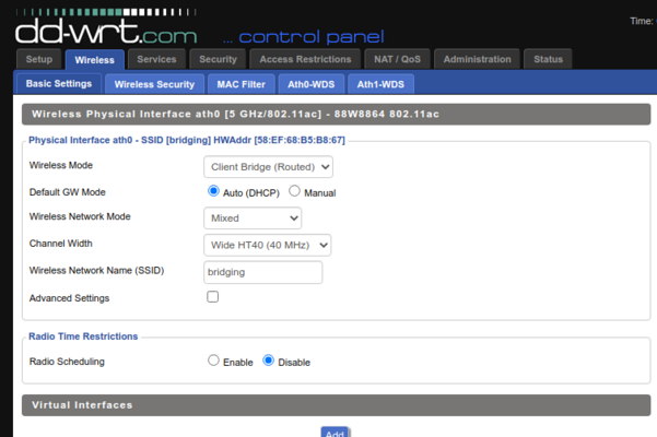
In this method of bridging the left most AP operates as a standard AP and the other rightmost AP is used in client bridged mode (Wireless->Basic-Settings->Wireless-Mode. Switch the mode from AP mode to Client Bridge. In this mode, the client bridge will act like a regular WiFi station and connect to the AP. As the devices we are using actually bridge the WiFi Chip and the LAN switch into one logical device, the PC shown on the right-hand side should be able to obtain an IP from the DHCP server running on the AP mode device.
Start by changing the IP address of the bridge that is going to be put into client mode. We cannot have two devices with the same IP so change it to 192.168.1.2. Be mindful that when you save and apply these IP address changes you will need to point your browser to the new IP address. So you now need to point your browser to 192.168.1.2.
You can modify the APs wireless modes by clicking on the wireless tab. Make sure that both of your SSID's/channels on the devices have been changed to the same value. Verify that the two APs are associated by clicking status->sys-info. If the APs are not showing as associated to one another, troubleshoot. The client bridged mode AP will now have its DHCP server switched off. Confirm this at status->sys-info. This device should still forward DHCP messages.
On both wired PC's do start->run and type cmd into the box that appears. Acquire new DHCP IP addresses by typing ipconfig /release then ipconfig /renew. Make sure that each PC acquires a new address and that every host can ping each other.
Bridge Performance
So now I would like you to test and try to increase the performance of your bridge. To test you should make one of the PCs in the above topology a Ubuntu Linux machine. Make sure the Ubuntu Linux machine gets an IP address on the 192.168.1.0/24 network. Then
sudo apt update
sudo apt install apache2
Now we are going to create a file of arbitrary size and put it in: /var/www/html/
You can create a file of a given size using:
dd if=/dev/zero of=output.dat bs=1M count=1000
Then copy it
sudo cp output.dat /var/www/html/
What is special about this directory? Why did we need sudo to copy it?
Now on you wired Windows PC on the other side of the bridge, you should open a web browser and type in 192.168.1.x/output.dat (Where x is the IP of the Ubuntu Linux machine).
What was the transmission speed. Can you change the Band, channel, channel width, or mode to increase the speed. You should try to picture the scenario where you are implementing this network for a client and would like to demonstrate that you have made all the changes and done all of the tests required to maximise the performance.
WDS (Wireless Distribution System) Bridging
Try to setup WDS bridging between the two APs. You can work out how to do this by reading the help pages in the router. Verify that your solution is working by pinging between the two hosts. Also make sure you only have one DHCP server active and that both PC's can obtain IP's from this one DCHP server.
- How does WDS differ from other methods of bridging?
Challenge 1: WDS Bridging with multiple APs
Groups of students can work together to create a large WDS bridged network. Remembering that WDS operates at layer two there are two ways that this lab can be configured.
- You can have one main node that serves as the root of the network. This will create a hub and spoke topology. The root node should have the MAC information of all other WDS bridges in the area. The other bridges should only include the MAC information of the root node.
- The second way that the lab can be configured is that each WDS AP can include the MAC information of all the other nodes in the network. This will create a full mesh. Remember that we are dealing with a layer two technology so you must ensure that STP (Spanning Tree Protocol) is turned on to prevent the formation of L2 loops.
Whichever method you choose you must ensure that each AP has a different IP address within the same subnet. Furthermore, you must also remember to have only one DHCP server. Set the other APs to DHCP forwarding mode.
Before finishing the lab, connect a wired PC to each WDS AP. Show that it can obtain a IP address dynamically and also that it can ping all other wired PCs in the network.
Challenge 2: Capturing WDS Frames
Capture some WDS frames using monitor mode. To get a client device in monitor mode, make sure you follow the instructions for the Alpha_USB_in_monitor_mode
- What do they look like?
Reset Factory Defaults
Remember to reset factory defaults when you finish.


